SorterBot
GitHub repo for my portion of the project
Introduction
SorterBot was a team project created for a control system design course. The goal was to sort items from one box to another based on their color. We decided that a RRP (2x rotational, 1x prismatic) robot with a SCARA configuration would be ideal for the task.
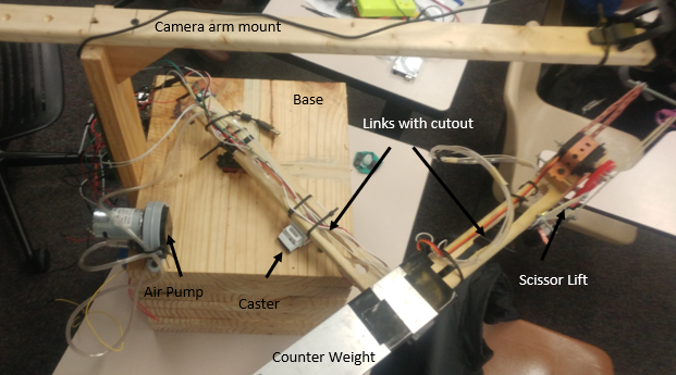
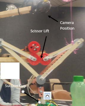
We considered a few different end effectors; in the end, we decided to use a suction cup as it would allow us to lift items regardless of their dimensions. All the items had flat surfaces suitable for the suction cup.
Although I assisted with the design and construction of the robot, my primary responsibility was to program the BeagleBoneBlack (BBB) portion of the robot’s software.
Programming
Because of the computer vision requirement, we decided to perform the image processing on a laptop and communicate the target coordinates to the BBB which would control the arm.
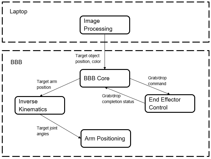
As seen from the diagram above, we decided to separate the behavior into four separate modules or nodes: inverse kinematics, arm positioning, end effector control, and a “BBB core” module to coordinate the other modules.
We used the Robot Operating System (ROS) framework to enable communications between all the parts of the program. The arrows in the diagram represent ROS messages being sent between different nodes.
I wrote the nodes that perform calculations in C++ for greater speed. Nodes that directly interfaced with the hardware (using GPIO or PWM) were written in Python to make use of the Adafruit BBIO library.
BBB Core Node
The BBB Core node coordinates the other nodes and implements the state machine that makes up the robot’s logic. The robot could be in any one of the following three states:
- Ready: This means the robot has no target selected. The core node is listening for a new target from the image processing node running on the laptop. Once it receives the pixel coordinates and color of the target object, the robot calculates the target location and enters the Retrieval state.
- Retrieval: The robot has a target selected and is moving to pick up the object. Once the end effector is positioned over the object, the core signals the end effector node to drop and attach to the target. If this is successful, the robot enters the Delivery state.
- Delivery: The robot has picked up the object and is moving to drop it into the correct box. Once the end effector is positioned over the drop zone, the core signals the end effector node to release the object. Upon dropping the object, the robot returns to the Ready state.
End Effector Control Node
The End Effector Control (EEC) node interfaces between the logic and the hardware of the end effector. It uses PWM to signal the servo raise and lower the suction cup, and a digital GPIO signal to switch the vacuum pump on and off. If the suction cup contacts a hard surface, the node detects this using a contact sensor.
If the EEC node receives a grab command, it lowers the suction cup until it either senses contact or detects that the suction cup has traveled too far without contact. If the suction cup makes contact, the node activates the vacuum pump. Finally, it raises the suction cup and reports success or failure.
If the EEC node receives a drop command, it simply turns off the vacuum pump.
Inverse Kinematics Node
The Inverse Kinematics (IK) node calculates the correct joint angles for the arm required for the end effector to reach a given (x,y) position.
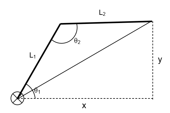
The second angle is calculated using the law of cosines, and the first angle is then calculated using the geometric constraints between x, y, and the angles:
\(x = L_1 \cos(\theta_1) - L_2 \cos(\theta_1 + \theta_2)\)
\(y = L_1 \sin(\theta_1) - L_2 \sin(\theta_1 + \theta_2)\)
Finally, the node makes sure that the position requested isn’t out of reach for the robot and doesn’t cause the robot to enter a singularity position.
Arm Positioning Node
The Arm Positioning node uses PWM to instruct the arm servos to move to a given angle.
Lessons and Future Improvements
A few lessons I learned from this project and things I would change if I were to redo it now:
- I would add better failure handling. In the original project, the robot naively reattempted any failed task with no attempt to readjust.
- Parameters that need to be tuned often should be passed in as arguments to avoid wasting time recompiling every time hardcoded parameters are adjusted.
- I would look for all-C++ libraries to greatly increase the speed of all processing.
Acknowledgments
- A. Bashkaran
- Image processing, object detection,
- Networking between the BBB and laptop
- Design, construction, and wiring
- M. Mandela
- Material selection
- Hardware
- Design and construction
- T. Foster
- Hardware acquisition
- Material selection
- Hardware
- Machining
- Design and construction
- J. Raval
- BeagleBoneBlack setup and programming
- Part selection
- Algorithm design
- Design, construction, and wiring: end effector design